
|
|
Site map :
Last upgrade to the site:
There has been
This is an unofficial LEGO® web site. Copyright 1996, 2000, Denis Cousineau
| A Turing machine is the simplest form of a computer. The concept was invented by Alan Turing in 1936. This was the first computer invented (on paper only). I- Principles of a Turing machine.In its simplest form, a Turing machine is composed of a "tape", a ribbon of paper of indefinite length. There is a "head" that can read the symbol, chose to write a new symbol in place, and then move left or right. The Turing machine is said to be in a certain "state". Finally, the program is a list of "transitions", that is a list that says, given a current state and a symbol currently under the head, what should be written on the tape, what state the machine should go, and whether the head should move left or right. The tape is used to store data. In addition, it can also store a series of transitions (a small programs) and thus, the head can run "sub-programs". We then say a Turing machine is emulating another one (the one on the tape). By analogy with modern computers, the tape is the memory and the head is the microprocessor. Although it is composed of pretty simple capabilities, Turing argued that this simple machine could performed any computation, that is, could realize anything that results from operations. In 1950, he discussed that the mind is itself the results of operations (at the neural level) and thus is the creator of the artificial intelligence studies. For examples, see :
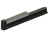
One way to know that a simple mechanism has the same computational capabilities than a Turing machine is to see if it can emulate a Turing machine. Only these mechanisms are powerful enough. Indirectly, it shows that humans are also Turing machines since we can emulate them. II- The Automaton with Append.I chose to implement in Lego a slightly different version of the original Turing machine. Instead of having a bi directional tape, it uses a stack. When the symbol beneath the stack is read (and removed), the machine changes "states" and can add zero, one or two symbols on top of the stack. This variation is maybe very different yet it is possible to show that this simple machine has the same capabilities than a Turing machine. Among other things, it can emulate a Turing machine placed on the stack. I programmed a small interface (through an Access database so Microsoft Access must be installed on your computer) to enter an test simple Automaton With Append (AWA or AAA in French). Follow this link to download the demo: AAA.zip. One reason to build the automaton with append instead of the original Turing machine was that I avoided building a bi directional (near) infinite tape. III- Building the automaton with LEGOIt turned out to be a very difficult project since, among other things, the construction needs to be "binary", that is, to be able to deliver one and only one symbol on the top of the stack, to pull one and only one symbol from beneath the stack, and that, for an indefinite period of time. In itself, adding a symbol is not that complicated, but doing this with "binary" precision is another matter entirely. a) the symbolsThe symbols themselves are made of cylinders. Using plates, I can code in binary so that the cylinder below is (1,0,1) or the number 5. This kind of bar code is easy to read using the light detector.
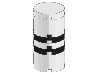
b) the memoryThe stack is a small hollow tower in which the symbols can fall horizontally. It is therefore a "compact" memory, containing near 10 bytes per 6 inches! Another difficulty is to make sure the symbols will always remain horizontal, which implies equal friction everywhere. Below is shown one section but many can be connected together. I used two sections (since I pretty much ran out of beams at that point).
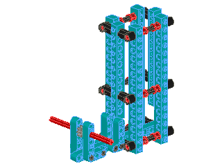
c) the readerThe reader is at the bottom of the memory. It is a mechanism meant to expulse one symbol at a time. The expulsed symbol pass in front of the light detector (not shown) so that the bar code can be read .
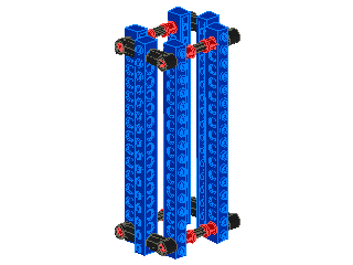
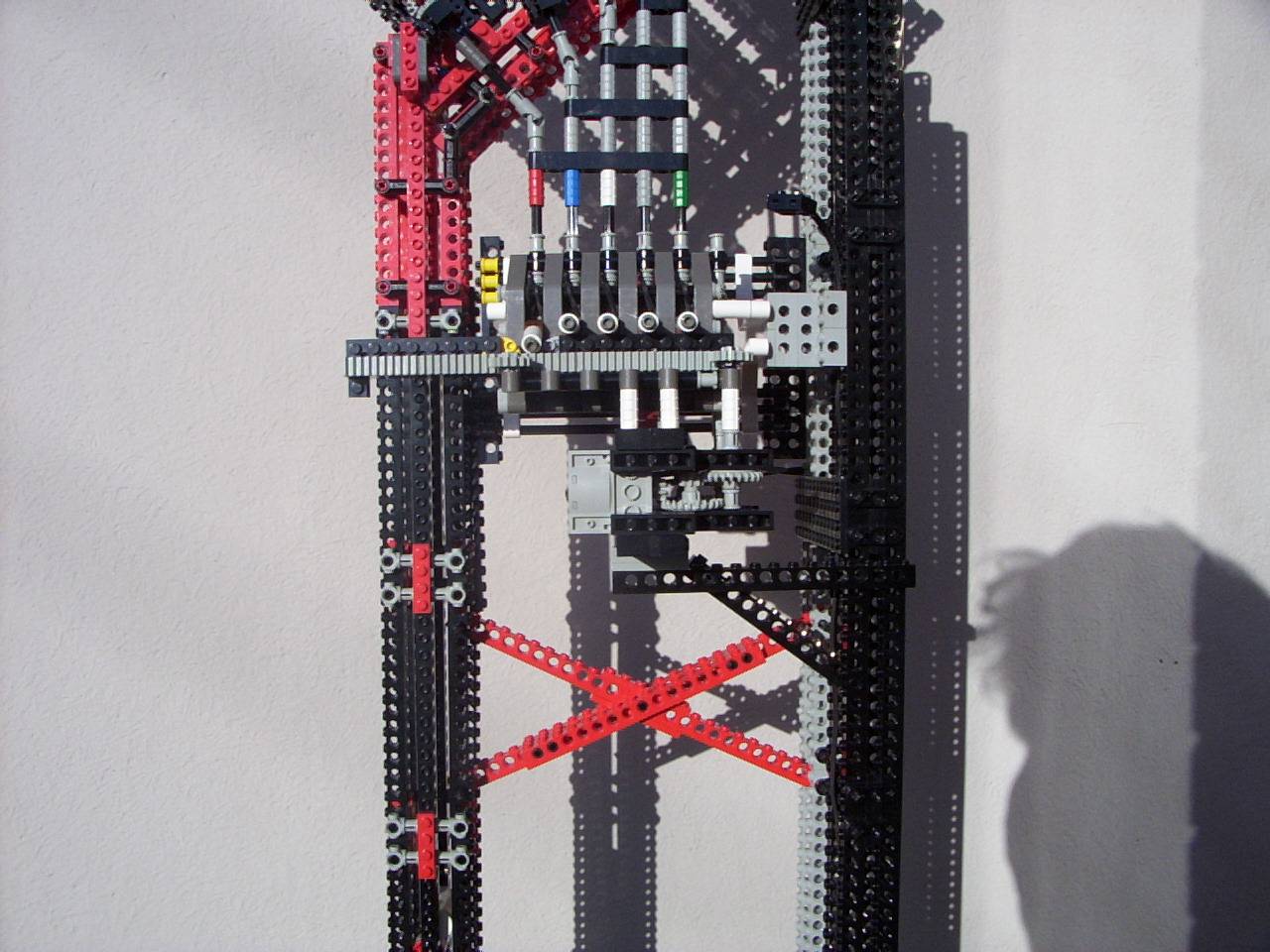
It is composed of the lower part of the memory stack and of a lever (shown on the side) that pushes the symbol out, activated in and out by the red axle. d) the stackerThe stacker is at the top. Its purpose is to place new symbols on the stack. It is maybe the most difficult part of the automaton. Only one bank is shown in the picture, but 5 were actually implemented (see pictures below).
It works using the two blue blades. Every time the blades turn 90 degrees, one symbol falls down the memory onto the stack. In order to turn exactly 90 degrees, I used the rotation sensor described in the section "Rotation sensor", connected onto the red axle for each bank. Since in the full implementation, there are 5 banks, the correct bank cannot be controlled directly from the RCX which has only three outputs. Therefore, a selector is required that can select, using one motors, which of (up to 5) output must be activated. I used the third design from the page on my 2-to-7 multiplexors. e- putting it all togetherAll
the designs shown above are available in LDRAW files: IV- ProgrammingWell, this Turing machine is not entirely mechanical... I used the RCX to store the transition table. Since the symbols are bar codes read with a light detector, it would have been very difficult to continue with a physical mechanism. Three subroutines are required, one to select which symbol to provide on top of the memory, one to turn the provider one quarter of a turn, and one to pull out one symbol from the bottom of the memory (reading it on the way). These routines were programmed using PRO-BOT. The subroutine Stacker turns the provider one quarter of a turn. It uses a sensor that turns off then on: Declare Stacker CONSTANT 2
BeginOfSub(Selecter) Declare Reader CONSTANT 4 A complete listing of the source code is provided in this text file: AAA.rcp. These three routines are the building blocks used in a main program that run the automaton. The main program can be generated automatically by the demo program indicated earlier, AAA.mdb. V- A full example: the AxnBxn problem.Suppose a very simple problem that we want to be solved by an automaton. We want a system that can decide whether the number of A's placed at the beginning of the input (on the memory stack) is the same as the number of B's following the A's. The symbol # indicates the end of the input. A simple way to program the automaton is to (i) read the first A, (ii) all the A's that follow are place back on the top of the stack, (iii) to read the first B, (iv) all the remaining B's are placed back on the top of the stack, and (v) once the end-of-input is reach, put it back on top of the stack, and start the program again on the resulting input. Basically, it creates a new input that has one A and one B less than the original input. A simple way to represent an automaton is with the following diagram:
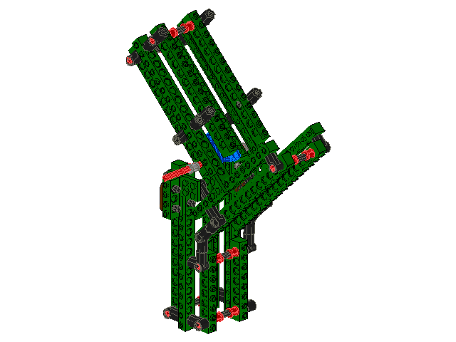
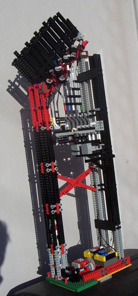
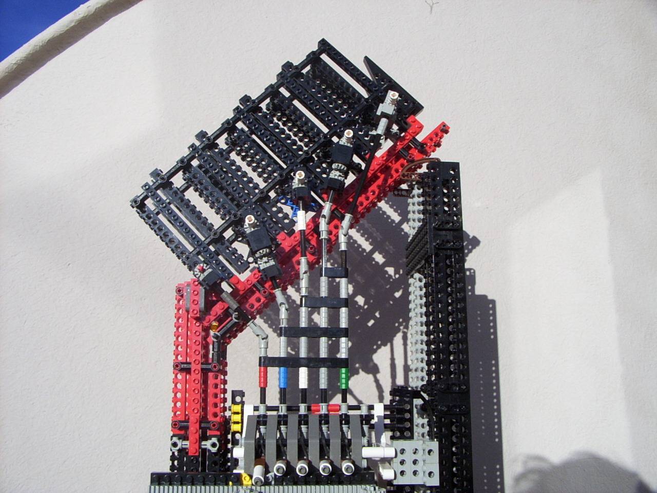
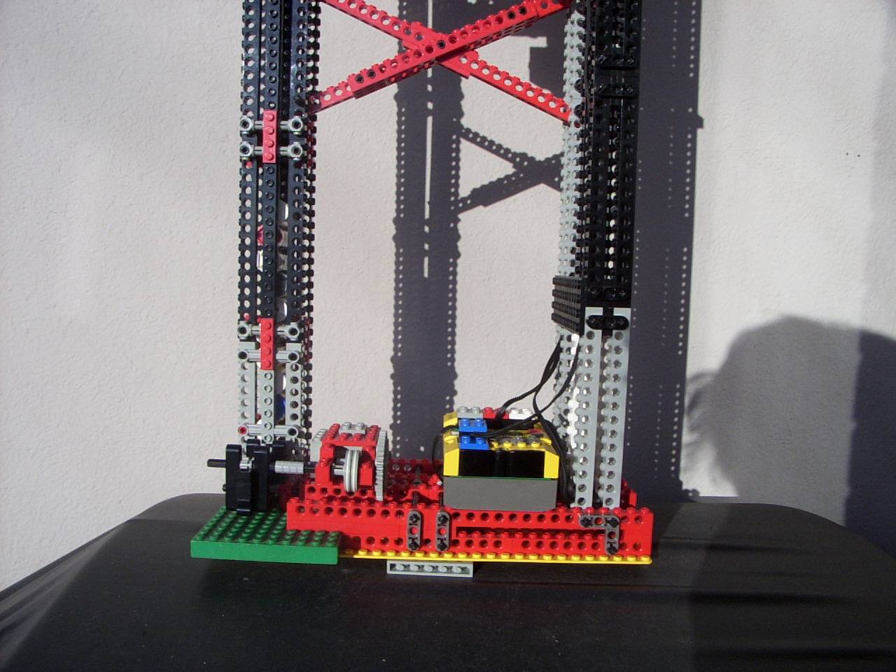
Where the > sign next to q0 indicates the starting state, and the double line around qexit indicates the accepting state, that is, the input was adequate. The branches depend on the symbol found on the memory (at the bottom of the stack). On occasion, there is an indication "stack an A" which means that the automaton is adding a symbol on top of the memory. Although this visual diagram is convenient to visualize the operations of the AxnBxn automaton, they are generally represented using the transition table, as follow: (q0, #) -> (nothing), (nothing), qExit where (nothing) means that nothing is added to the stack. You can check that both representation have the same meaning. The RCX program that will run this automaton is generated by the AAA.mdb demo program, and the result is: { Mapping of the internal states to a numeric value: } This program is saved by AAA.mdb under the name of AAA_2.rcp, which is automatically inserted in the global program AAA.rcp. IV- My implementationHere is the final result:
Not exactly small, and the colors don't really match (I barely have enough LEGO to make it all ;-) ). Below are more details, break down in three pictures. Click to enlarge.
IIV: What can we learn from Turing machines?The main question is related to artificial intelligence. The Turing machine can perform any computation. Well, does the brain performs computations? If so, it is possible to imagine one day a computer that will have the same cognitive capabilities than a human. We could converse with it, it could discover new insight about physics, about the human nature... For more, check the Loebner Prize.
|
|