The 1-to-2 multiplexor can multiply by two the RCX outputs. However, these
outputs are slow, so we would like to keep one output straight, and have the
other one controlling stuff where speed is not crucial.
The following devices can control up to 7 motors. They can be extended
to 9 without any changes. However, they are controlled using two of the RCX
output. Therefore, there is only one remaining output on the RCX.
The general idea is to have a kind of selector that can divert one motor
onto one of seven possible gear, the actual output. The second motor (motor B)
can then be turned on, forward or backward.
Design I
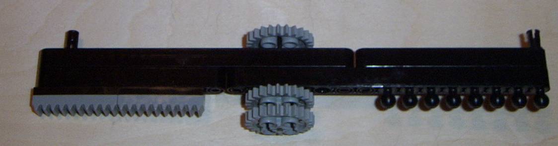
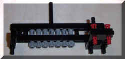
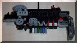
In order to do so, the following mechanism uses a horizontal slider that
can move left or right:
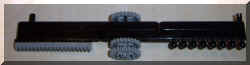
The back gear touches Motor B, whatever position it is on, using this back:
Motor B connects on top of the Figure and makes all the 8-teeth gears turn.
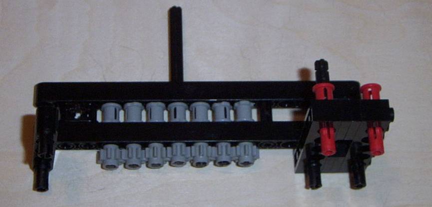
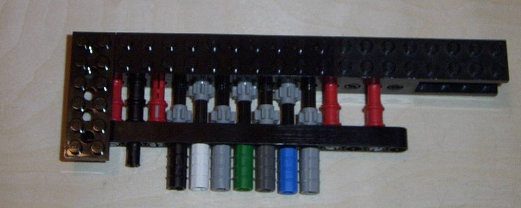
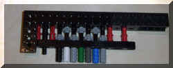
The front of the slider connects to one of the 7 outputs, and only one at a
time, depending on its position on the front part:
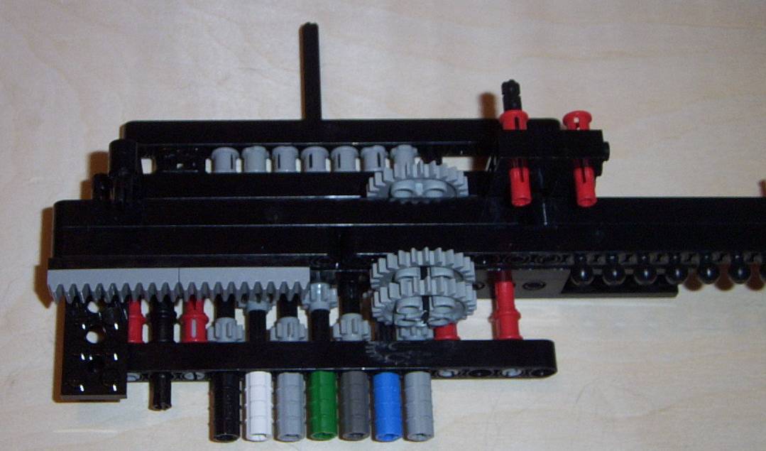
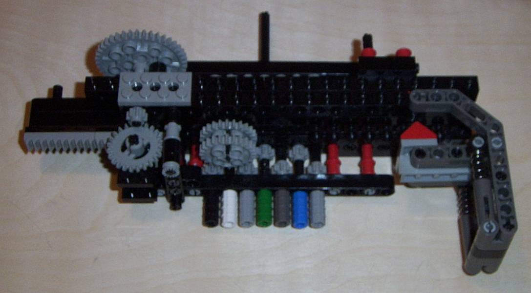
Connecting these three parts, we obtain:
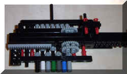
The slider can move left or right owing to the rack on its side, which
connects to the motor A. On the right of the slider, we can see
"balls". The are use to make the slider stops at a correct position
and not in-between (otherwise, Motor B is jammed).
The above picture shows the stepper added to block the "balls" at
legal positions (see pages on stepper motors). Are missing the motor B on the
back and motor A on the top.
Design II
The following design is much more compact but requires many of the new Lego
beams (with no studs on it).
The POV rendering shows the same with the slider placed in front of it. The
LDRAW plans are provided in this file: multi_v2.dat
Design III
This is the best design so far. The trouble with Design I and II is that
the gears don't always mesh perfectly. Thus, on some occasion, two tooth
arrive head-to-head (so to speak). Then, a lot of torque is required to move
the slider in its position. Since these events are unpredictable, it means
that on some occasion, the motor that moves the slider left or right will not
be strong enough, and the slider will no longer be aligned. Using a sensor of
some kind would alleviate this problem. Yet, I prefer to have a design which
does not have this problem so that I can use a sensor elsewhere.
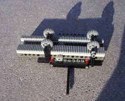
The following design does not have this problem. It is based on the gearbox
pieces:
The gray gear in front is turned. However, as long as the lever arm is not
pushed back, this has no influence on the output (here, the output would be
the black axle in the front of the picture). This arrangement can be repeated
many times (5 times below).
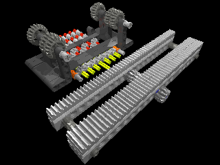
Using rubber bands, the levers tend to go back. I used a slider which
allows only one lever to be in the back position at a time, thus engaging a
single output at a time.
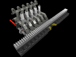
Here, the slider is shows in front of the multiplexor, but should be
inserted behind the levers, mounted with white tubes. Finally, the red axle is
the input, turning all the gray gears.
The full design is shown in multi_v3.dat
Mario Ferrari published a prototype similar to Design I in his book. However, it has
some drawbacks. a) the slider was too tightly hold, requiring a very strong
motor to make it turn; b) it was limited to only 5 outputs, and difficult to
expand; but more importantly, c) it required a RCX input (a touch sensor) to
detect when the slider is in a legal position. The design III does
not need a sensor to stop the slider in a good position. Timing is
sufficiently accurate.