Site map :

Last upgrade to the site:
august 10th, 2002.

There has been

access to my Lego pages since creation.
This is an unofficial LEGO® web site.
LEGO® is a trademark of the LEGO® Group of companies
which does not sponsor, authorize or endorse this site.
You can visit the official LEGO website at: http://www.lego.com
Copyright 1996, 2000, Denis Cousineau
| |
In a 1- to- 2 multiplexor, what is important is the sequence of on and off
sent by the RCX to the multiplexor that will determine which motor to turn on
and in which direction.
In the following, I use the notation:
 | 0 to indicate a OFF output, |
| +1 for an output ON in forward mode, and |
| -1 for an output ON in backward mode. |
The following table summarizes the expected behavior of
the 1-to-2 multiplexor:
| |
Motors
must be |
| RCX
outputs |
A |
B |
| 0 |
0 |
0 |
| +1-1 |
+1 |
0 |
| +1+1-1 |
0 |
-1 |
| +1+1+1-1 |
-1 |
0 |
| +1+1+1+1-1 |
0 |
-1 |
In this situation, the -1 is a sort of marker that ends the sequence. At that
time, the order is activated, turning one of the motor ON.
The 1- to- 2 multiplexors can control the
motors A and B in any possible combination of ON and OFF. There could even be
sequences where both motors A and B are ON simultaneously (although I did not
explore this possibility here. On the negative side however, 1-to-2 multiplexors are slower to react since they must receive a full sequence, and
if the RCX is sending this sequence, the programming is more complex.
Implementing a 1-to-2 multiplexor
I built a 1- to- 2 multiplexor using Lego.
It worked great, but it is quit slow, each of the +1 in the sequence
requiring about 1 second, a typical sequence composed of three signals
imposed a three second delay. This is not for robots that have to react
rapidly...
This "multiplexor" (any better name?) s'idea steam from the fact that Lego switches have 4 positions.
So if I place two such switch with a 45 degree difference, I would have 8 full
positions, including: left switch on_forward, right switch on_forward, etc.
With a device that could turn these switches exactly 45 degree, I could select
which motor could be on, and in what direction. Exactly 45 degree is the
difficult part here, since I don't want to use a sensor on the RCX. I need a
blind mechanical device that will always turn sharp 45 degree.
The second thing is that I do not have switch off positions, since when one
switch is off, the other is on. So I needed a main switch that I could turn on
when the rotation switches are at the right angle. I could do this using
a ratchet (see ratchet subsection). If my driver is turning
counterclockwise, it adjusts the position of the rotation switches, if the
driver is turning clockwise, it is turning on the main switch. A shock
close the main switch if the driver is turned off.
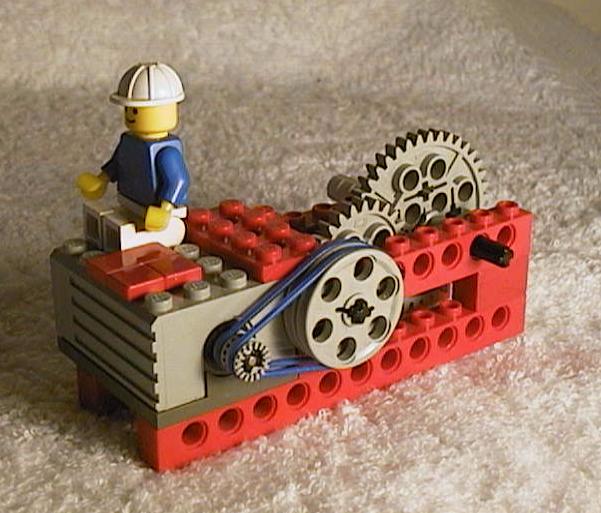
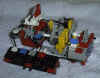
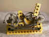
The resulting mechanical device is given below. It is rather large,
but works pretty well. Of course, the RCX needs to know how long to turn
on the driver (the motor under the minifig).
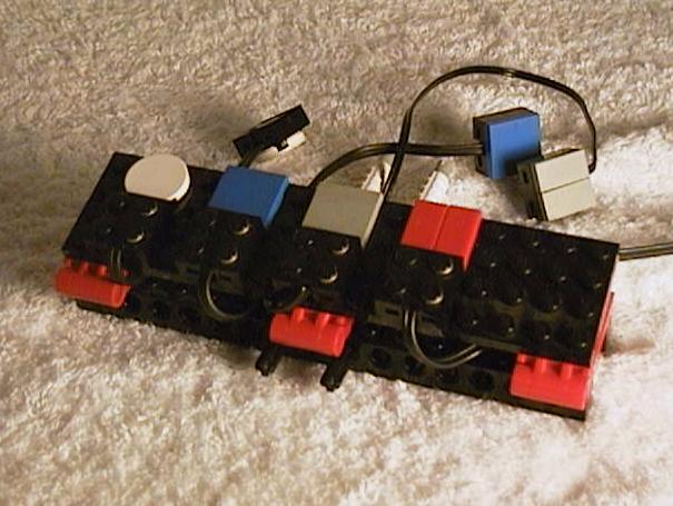
To give you an intuition of its functioning, when you want to run either
motor A or motor B (connected to the white and the blue chips respectively),
you send pulses to the 8-tooth star on the left, like on old pulse phone, when
you dial a number. Then, after the selection is completed (up to four pulses),
you turn the main switch, located on the back (gray chip).
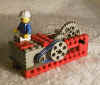
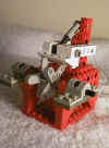
- The driver. This is essentially the same gear reduction as
for the pump above. It can turn in either direction, with enough torque to
control the ratchets.
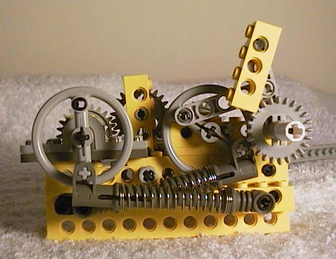
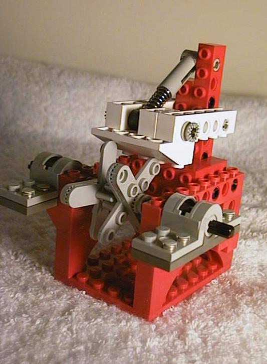
- The selector and the main switch. On the front view, we see an
unusual ratchet (see Baum's book) that either activate the left part (the
selector) if the driver is turning counterclockwise, of the right part
(the main switch) if the driver is turning clockwise. On the back,
we see that the main switch (now on the left) is connected to a shock so
that it will revert to off position if the driver is shut down. The
selector (now on the right) is made of another ratchet (the yellow beam on
top) that will turn the crown gear approximately 45 degree when the driver
is shut down (because of a second shock).
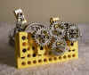
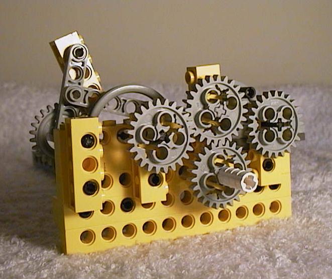
- The stepper motor. The above ratchet is only
approximate. I needed a further device that will stop the ratchet at
exactly 45 degree turns. This is done using a stepper motor (based
on a 8-tooth star with a
shock putting pressure on it, so that it is unlikely that it will stop at
odds positions - see stepper motor subsection). Also the position switches are visible. Note
that the axle to the right is 45 degree out of phase with the axle going
out from the left. This magic was obtained by putting together two
helicopter shaft (piece number 2479)
- Connection pad: This pad is only for increasing clarity; there is
many wires going to this place, and it become rapidly confusing.
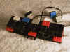
Connection: the gray chip is connected to a power source that is always on.
This in turn feeds the main switch. The output will either be the white or the
blue chip. The driver (red chip) is connected to the RCX.
|